Breadboard Thoughts and Ideas
Overview – I wanted to share some of my thoughts and ideas on using a breadboard that I’ve gathered since 2016 when I first got into building guitar pedals. Something that I feel isn’t stated often enough is that using a breadboard for electronics is pretty difficult, especially for beginners. There is a fairly steep learning curve and even a relatively simple schematic like the Fuzz Face was challenging and quite frustrating for me to initially figure out. I’ve been able to learn and apply different techniques which have benefited me greatly, and because of this, I’m now working on my second guitar pedal for production which is called the Spellbook. To see the completed version, check out this page.
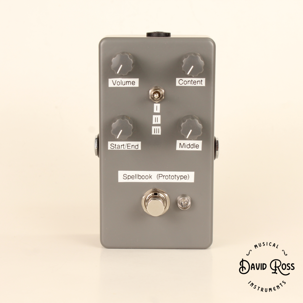
I would not have been able to do so without a solid foundation in breadboarding. The following is a compilation of what I’ve learned over time, which will hopefully help those at the beginner and intermediate level, and also give some ideas to the more advanced breadboarders out there.
High quality breadboard(s) – When I was first starting out I bought a couple of cheap non-brand name breadboards thinking that they would work as well as any other, and that all breadboards would be roughly the same in terms of quality. I was mistaken. Circuit layout and design is difficult enough already. One of the most frustrating things about breadboarding is having the circuit laid out correctly, only to realize that the breadboard itself is intermittent or has dead spots. Another issue I’ve found with cheap breadboards is that they don’t take component leads well. Some of the slots work OK, others are too loose or too tight. I use the Jameco Valuepro 830-Point Solderless Breadboard and they’ve performed flawlessly since I bought them about two years ago. They are worth the extra few dollars it in my experience.
Amount of breadboards – This really comes down to personal preference. If you’re a beginner doing circuits like the Electro-Harmonix Big Muff Pi, ProCo RAT, or Sola Sound Tone Bender, you’ll really only need one to start out with. As you start to get into more elaborate circuits, you should consider using two, possibly more. Here’s a picture of a PT2399 delay that I did a while ago using two breadboards:
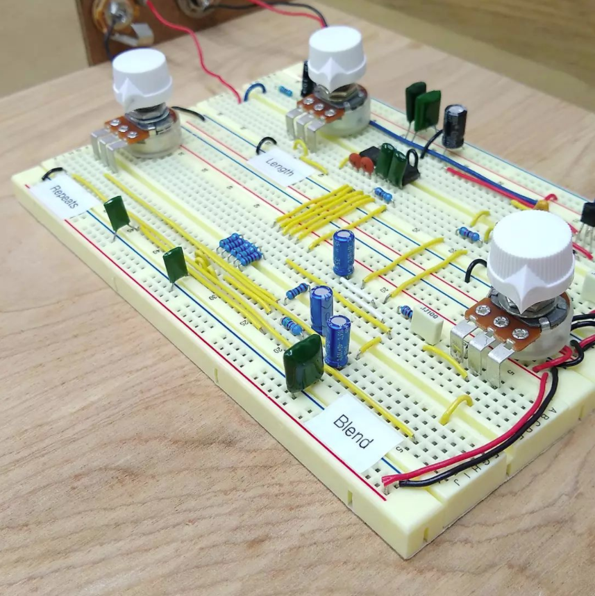
The neatness is rather extreme here but I found this circuit to be rather difficult to layout due to parts being connected at different points. Overall, having two boards made things less cluttered, easier to layout, and easier to troubleshoot. I currently am using three breadboards and may add a forth in the future.
Wiring – I like to use a combination or wire types for creating circuits on my breadboard. I use generic breadboard jumper wires for spanning long distances (you can pick up a pack of 100 for about $10 or so), I use solid core wire for spanning shorter distances between components. I use this type of wire 90% of the time and keep it in a container. I like to use stranded core wire for any wires that I have to move around. An example of this would be if I want to move the wire coming from the input jack to another part of the breadboard. Additionally, I like to color coordinate my wires which helps track down issues if they occur. I like to use black for ground, red for power, blue or green for signal path, and yellow for everything else. You don’t need to go overboard here but it’s helpful to be organized.
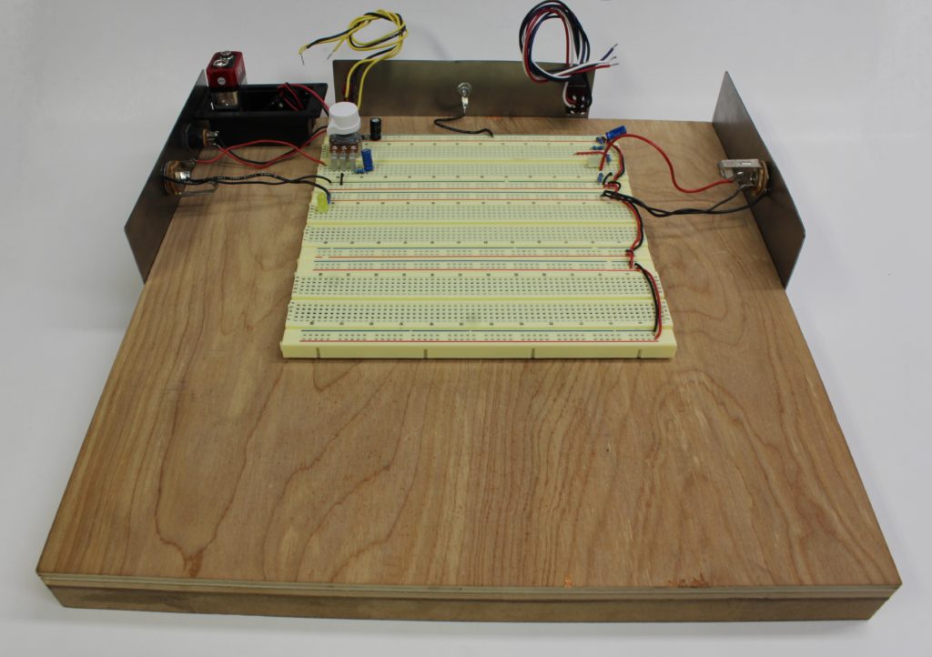
Setting it up – When I first started out I would have my breadboard sitting on my desk with everything dangling off of it. This included pots, jacks, switches, battery, etc… I realized quickly that this was not ideal because invariably it would get bumped, fall, slide around, or have some lead get ripped out of the board which would cause the circuit to fail. I decided to design a platform for the breadboard to sit on so I wouldn’t have these problems. I ended up using a 12” x 12” piece of thin plywood screwed to some 3/4” MDF which acts as a frame. I then attached the breadboard with double sided tape to the top. Here’s what it looks like:
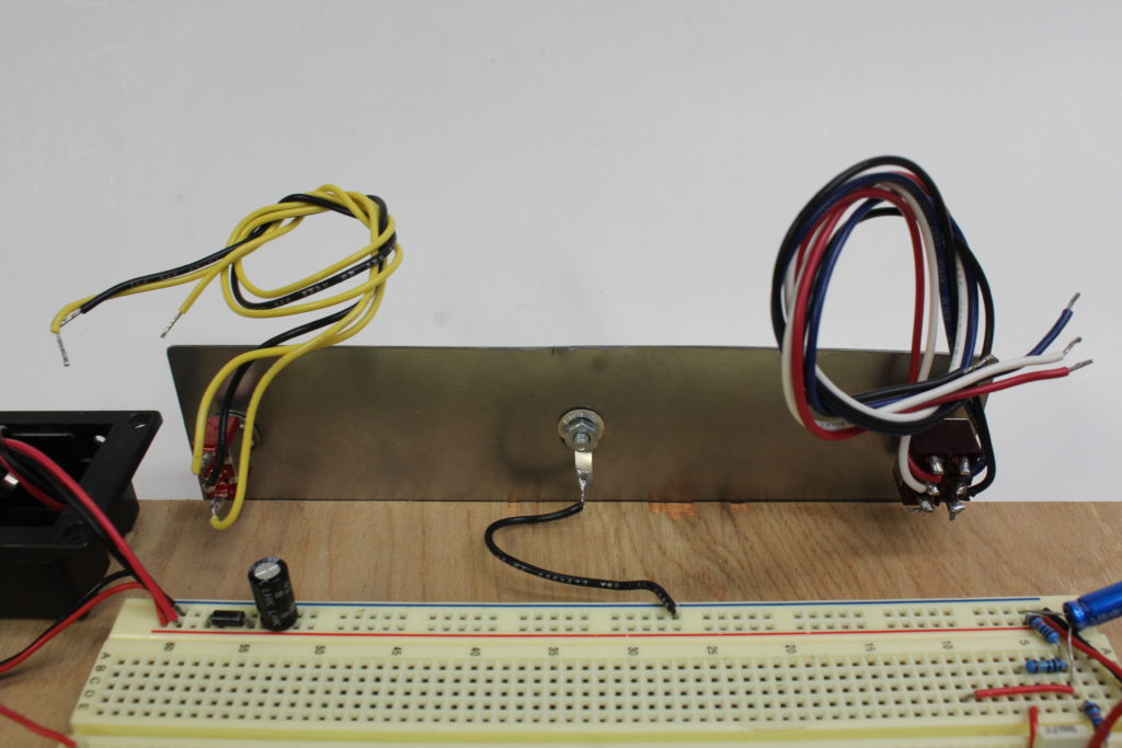
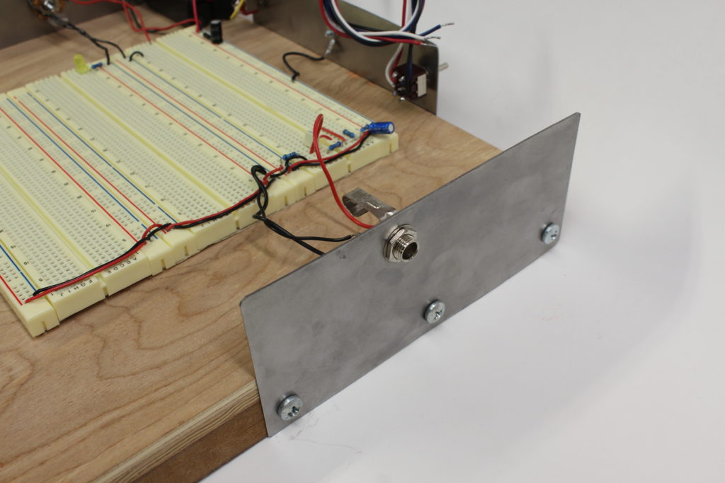
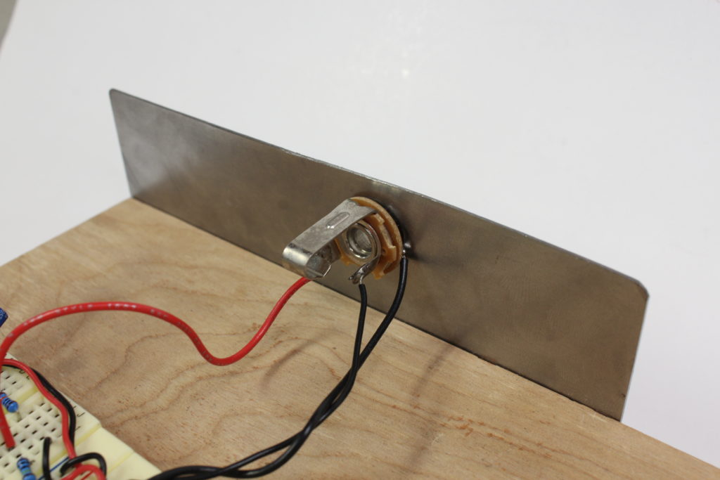
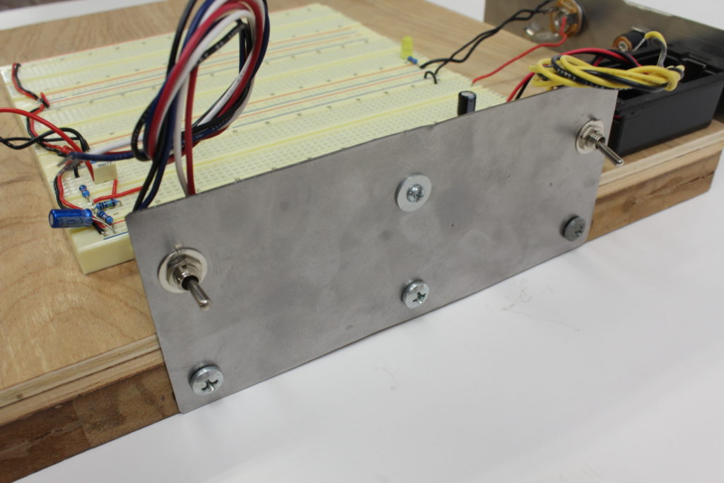
Noise – An issue I was having up until recently was where I would set up my circuit, expect it to work perfectly, only to have there be some strange noise, oscillation, or bleed in the signal occur. Breadboards typically are susceptible to noise because the components and leads are out in the open as opposed to being in an enclosure. I found that most of my issues were not a result of this. What I realized was that I wasn’t grounding the cases of my jacks and switches, and this caused the strange behavior. I decided to remedy this by cutting some thin sheet metal, drilling it out, and attaching it to the sides of my breadboard platform. I then ran a wire from each of these to ground on my breadboard and this solved a lot of those types of problems. Here are a few pictures of what I mean:
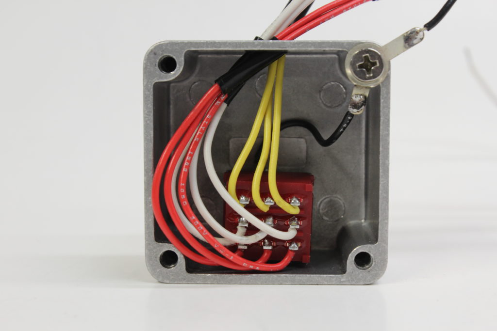
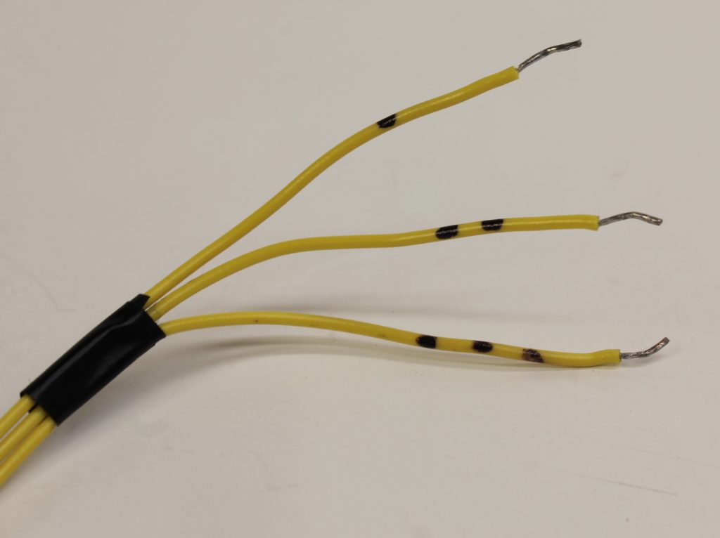
Footswitches – In the past I would often design a circuit without considering the footswitch. I would assume that whatever footswitch I decided to use would play nice with the circuit, which often was not the case. Additionally, I was content with having it dangling off the breadboard and engaged the switch by pressing it with my fingers. This was never convenient or ideal and so I decided to do something about it. I purchased a few 1590LB enclosures, drilled them out, and added footswitches. I ran the leads out of the front and made sure to ground the enclosure. I even came up with a ledger to indicate what wires go where. This allows me to set it up quickly and easily, while also having it be very stable. Here’s how I did it:
Tools – There are very few tools that I use for breadboarding but they all have their place. A soldering iron (preferably with a temperature setting) and high quality solder are a must for tinning leads, attaching leads to switches, pots, and alike. This is also necessary to have if like myself, you’re into guitar repair. Furthermore, I’d like to put an emphasis on “high quality” for the solder because much like the breadboard itself, you’ll save yourself a lot of hassle by not buying the cheap stuff. Cheap solder doesn’t flow well, it bunches up into chunks, and is junk in my experience, especially cheap lead-free solder. I personally use Kester 24-6337-8800 solder. While it is expensive, it should last years before you need to replace it. The only other tools I would suggest are a pair of wire strippers, flush cutters, needle nose pliers, sockets, and wire (which I covered above).
Laying out circuits and further considerations – The last thing I’ll touch on is how I like to lay out a circuit. I have a standard way of doing things starting with the power supply. You can see here that I start with a voltage protection diode (1N5819) running in series, followed by a 100uF capacitor to ground to filter the power supply. On the other end of the breadboard I have a voltage divider with another filter capacitor which allows for a 4.5V tap. Here are some pictures of what I mean, along with a schematic:
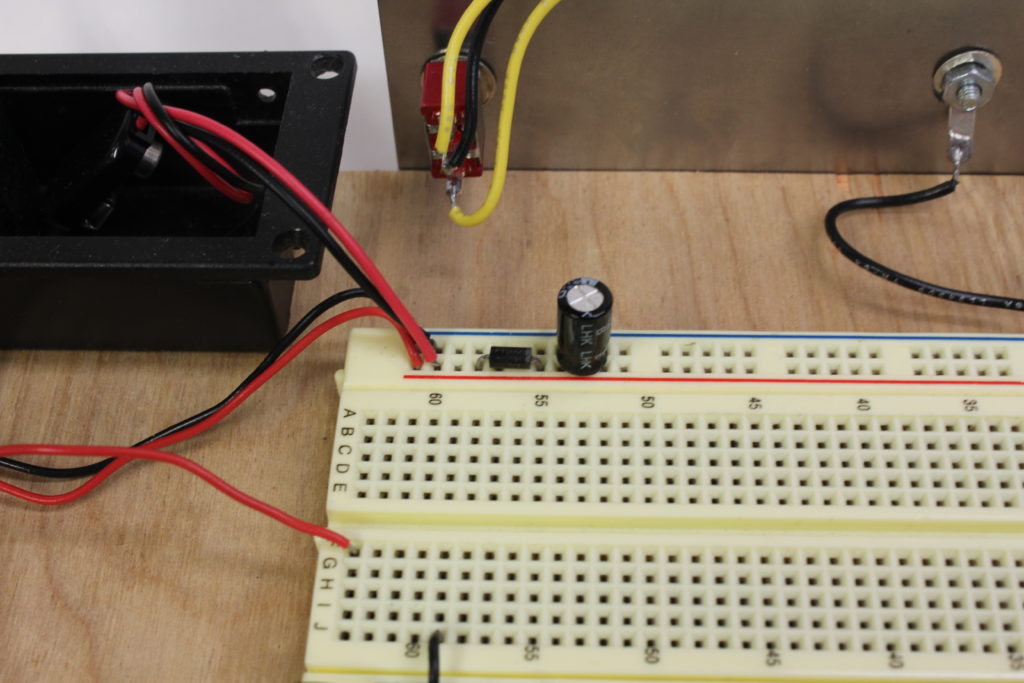
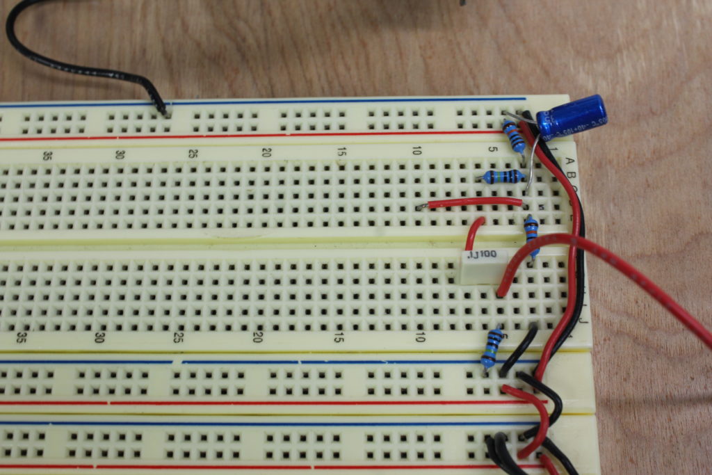
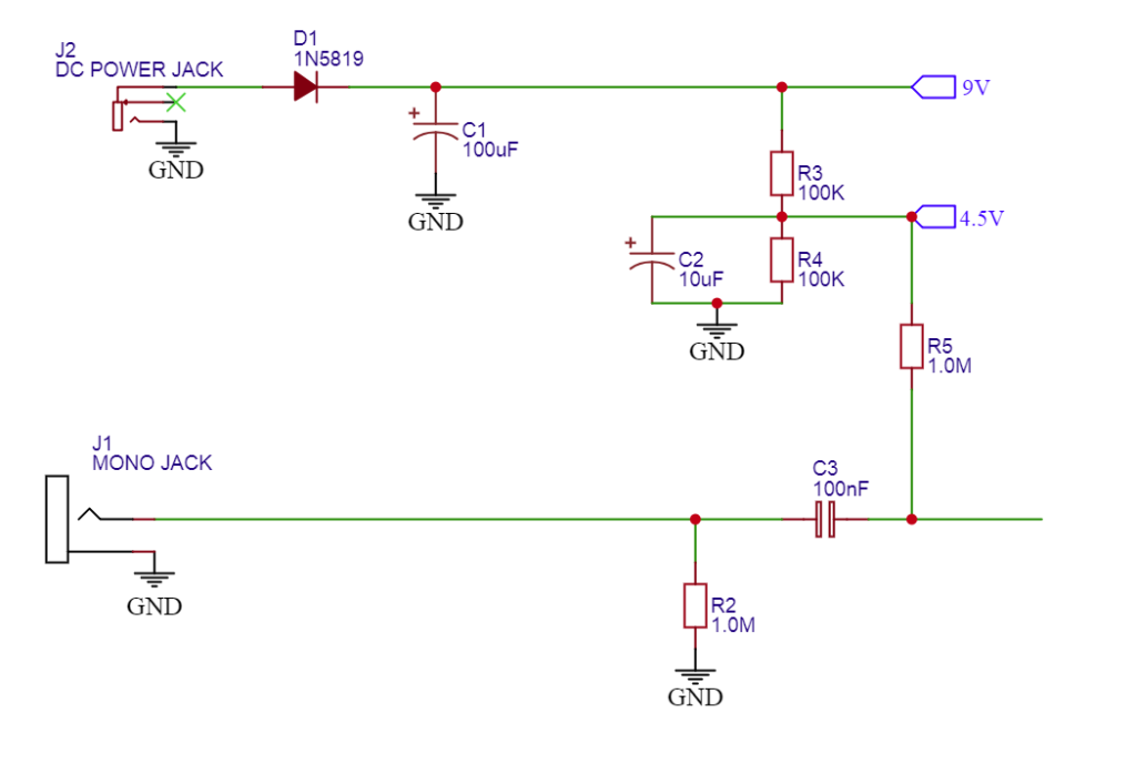
I have this set up as a permanent feature because I use op-amps regularly. In addition, one thing that I like to do is setup my circuits with nicely trimmed leads for the components. I see a lot of people just bending the leads and placing them in the slots but I find that trimming the leads allows for a neater setup and you don’t run the risk of leads touching and shorting out your circuit. You can still use the components later on even if they’re trimmed.
Conclusion – I hope that what I’ve written will save you some trouble and give you some encouragement moving forward. This setup has really helped me when designing guitar effects pedals and I hope the information helps you too. If you have any questions or comments, feel free to message me through the Contact page and I’ll get back to you. Thank you!
-David